|
|
Toshiba Satellite L25 disassembly.
|
|
|
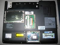 |
STEP 1
Remove the plastic covers for the Hard Drive, RAM, and WiFi card. Remove all the screws on the underside of the laptop that are recessed into the plastic frame. |
| |
|
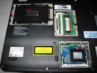 |
STEP 2
Remove the RAM by pushing the two tabs away from each other. To remove the Hard Drive, unscrew the screw circled in red first, then pull on the plastic tab to pull the Hard Drive out of the IDE connector slot. *For the WiFi card, if you feel comfortable taking off the two connectors circled in red, then do so in order to remove the WiFi card. I personally was not comfortable taking them off because they are so small. I will explain later on how to remove the WiFi card later on if you do not remove it in this step.* |
| |
|
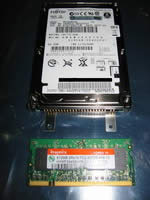 |
STEP 3
Here is a picture of the Hard Drive and the RAM. Please place them where they are safe from ESD (anti-static bag, piece of cardboard, etc.) |
| |
|
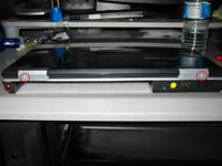 |
STEP 4
On the backside of the laptop remove the 3 screws that are circled in red. |
| |
|
 |
STEP 5
In the battery compartment area unscrew the screws that are circled in red. Then open the laptop screen slightly so that the whole laptop is in an upside down "V" shape. Unhook the plastic tabs circled in green. |
| |
|
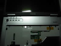 |
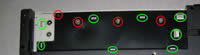
STEP 6
Open the screen all the way so that it is parallel with the main body of the laptop. Gently take off the plastic piece above the keyboard by lifting it up. |
| |
|
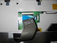 |
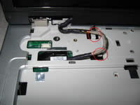
STEP 7
Lift the keyboard up and flip it over. Disconnect the ribbon cable by pulling on the blue plastic tab. Also disconnect the white ribbon cable as well.
|
| |
|
|
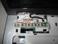
STEP 8
Remove the three screws circled in red. *If you didn't remove the WiFi card from earlier, move the cables in the green area out of the way and cut the plastic with a pair of wire snips.* |
| |
|
 |
STEP 9
Unscrew the two screws that are circled in red. Gently remove the PCB by lifting it straight up.
|
| |
|
 |
STEP 10
Gently unhook the video cable from the two plastic tabs circled in red. |
| |
|
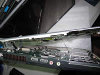 |
STEP 11
Place the laptop on its side with the optical drive facing down. You will see one or two cables (depending if you removed the WiFi card) that are attached to both the top and bottom portions of the laptop. One is the video cable for the display, while the other is the cable that goes to the WiFi card.
|
| |
|
 |
STEP 12
Remove the video cable by unhooking the tab to the connector as shown in red. |
| |
|
 |
STEP 13
If you didn't remove the WiFi card from earlier, get a box of around 4-6 inches in height so that you can elevate the bottom portion of the laptop from tugging on the WiFi card cables. Rotate the bottom portion of the laptop so that there isn't any strain on the WiFi card cables.
|
| |
|
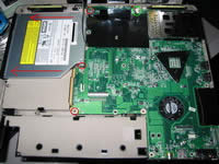 |
STEP 14
Remove the three screws circled in red (one of them is on the optical drive bracket) and disconnect the connector circled in green. Remove the optical drive by pulling the drive away from the motherboard. Also remove the 2 nuts on the RGB monitor connector on the side of the laptop (not pictured). Lift the motherboard up from the left side as pictured slightly and pull out the motherboard gently. |
| |
|
 |
STEP 15
Flip over the motherboard carefully. If you haven't removed the WiFi card from earlier, you can do so now ;-) You can also set aside the laptop display somewhere safe. |
| |
|
|
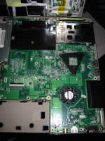
STEP 16
You can now lay the motherboard down elsewhere to work on. |
| |
|
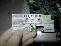 |
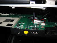
STEP 17
Here is a picture of the label for the riser card on the bottom corner of the motherboard. Doing a Google search reveals that the riser card is for the dial-up modem. |
| |
|
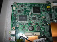 |
STEP 18
In this picture the following is visible: Realtek 10/100 LAN controller chip, Texas Instruments PCMCIA Card controller chip, and the BIOS chip soldered onto the motherboard.
|
| |
|
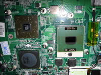 |
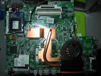
STEP 19
Here is a picture of the CPU/Northbridge/Southbridge with the old thermal compound cleaned off. The CPU is a Dothan-based Celeron M 370 (90nm) running at 1.5ghz (15 X 100mhz), mPGA-479M package, 1mb L2 cache, and a voltage of 1.245v (according to software). The chipset is a ATI Radeon Xpress 200M chipset composing of the SB400 Southbridge. I could not identify the Northbridge since the text is so tiny. |
| |
|
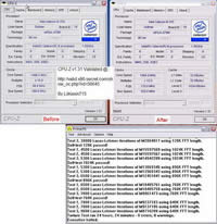 |
STEP 20
Besides reapplying thermal paste such as Ceramique made by Arctic Silver, what else can be done? How about a little bit of overclocking fun? With the help of (sorry, the page is gone) technical guide I was able to overclock the Celeron M 370 CPU! The pin-mod forces 100 MHz bus socket 479 CPU's to run 133 MHz bus speed. With the pin-mod the new clock speed is now 15 X 133 MHz = 1995 MHz, a 500mhz overclock! Pictured are before and after screenshots of CPU-Z. As with any type of overclocking stability cannot be guaranteed so proceed at your own risk! My CPU was able to run Prime 95 Large FFT Test for 24 hours without any instability as pictured. If your CPU cannot run stable at the overclocked speeds, you WILL have to take apart your laptop and remove the wire. TIP: if you do perform the pin-mod, make sure the CPU is seated in the socket all the way. The pin-mod might slightly elevate the CPU from not being inserted into the CPU socket all the way because of the wire. If this happens you can push down on the green part of the CPU to force the CPU into the socket all the way. |
| |
|
|
|


