|
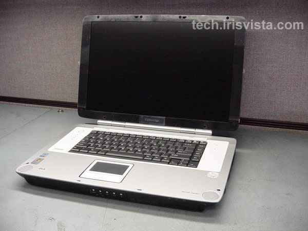
Toshiba Satellite P25 P20 disassembly. |
|
|
 |
STEP 1
Turn the unit upside down.
Remove the battery.
Remove the DVD drive.
Remove two screws securing the hard drive and lift it off.
|
| |
|
 |
STEP 2
Remove six screws securing the modem card cover, wireless card cover, memory card cover.
Remove all covers.
|
| |
|
 |
STEP 3
Disconnect the wireless card cables and remove the wireless card.
Remove the memory module. |
| |
|
 |
STEP 4
Remove five screws securing the CPU cover.
Remove the cover. |
| |
|
 |
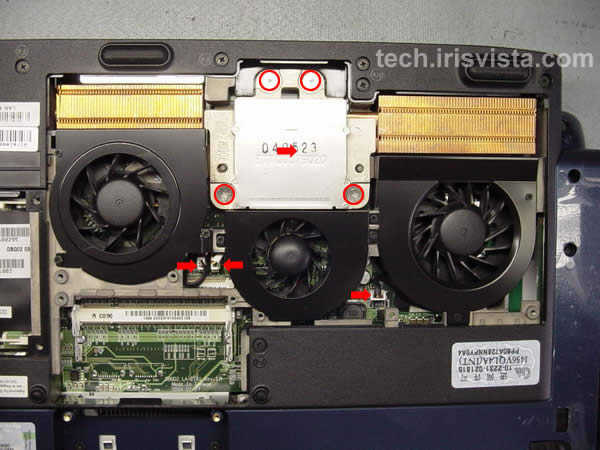
STEP 5
Remove four screws securing the heatsink.
Lift off the heatsink.
Disconnect three fan cables on the system board.
|
| |
|
 |
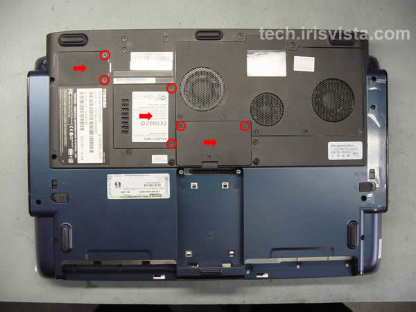
STEP 6
Removed all marked screws on the bottom of the computer.
|
| |
|
 |
STEP 7
Turn the laptop right side up.
Insert a thin object under the securing strip and lift it up.
Be careful, it may be very tight.
|
| |
|
 |
STEP 8
Work with a guitar pick to release the latches. Be careful, do not brake too many latches. :)
|
| |
|
 |
STEP 9
Remove the securing strip. |
| |
|
|
STEP 10
Remove two screws securing the keyboard.
|
| |
|
 |
STEP 11
Disconnect the keyboard cable on the system board.
Remove the keyboard.
|
| |
|
 |
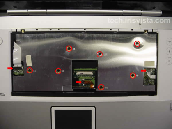
STEP 12
Remove seven screws securing the top cover assembly.
Disconnect the power button cable, touchpad cable and function cable on the system board.
|
| |
|
 |
STEP 13
Work with a guitar pick to disengage the latches.
|
| |
|
 |
STEP 14
Lift the top cover assembly off the base. |
| |
|
 |
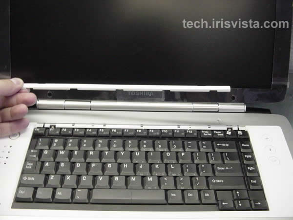
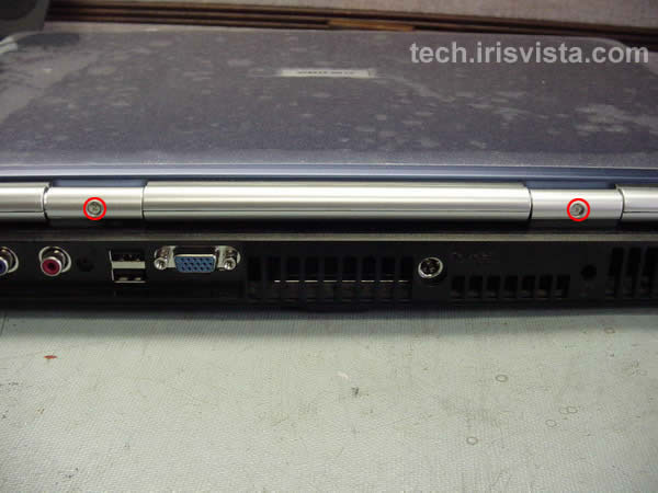
STEP 15
Remove two screws from the back of the hinges.
|
| |
|
 |
STEP 16
Remove four screws from the hinges cover.
|
| |
|
 |
STEP 17
Remove the cover. |
| |
|
 |
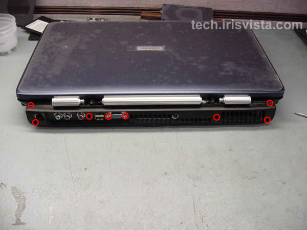
STEP 18
Remove six screws and two hex studs on the back of the laptop. |
|
| |
|
 |
STEP 19
Remove one screw securing the back cover. |
| |
|
 |
STEP 20
Remove two screws from the hinges.
Disconnect the display cable.
Release the wireless cables.
|
| |
|
|
STEP 21
Lift the LCD assembly off the base and remove it.
Go to another guide for screen removal instructions.
|
| |
|
 |
STEP 22
Remove one more screw securing the back cover.
|
| |
|
 |
STEP 23
Remove the back cover.
|
| |
|
 |
STEP 24
Lift the tape covering the connectors. |
| |
|
 |
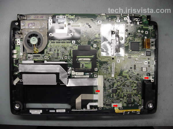
STEP 25
Disconnect five cables from the system board.
Remove three screws securing the system board. |
| |
|
 |
STEP 26
Lift off the system board.
|
| |
|
 |
STEP 27
Remove two screws securing the modem card, disconnect the cable and lift off the modem.
Unlock the CPU lock and lift it off the system board.
|
| |
|
 |
STEP 28
DONE !!!! |
| |
|
|
|