 |
Toshiba Satellite A135 A130 disassembly. |
|
|
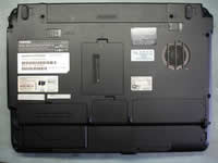 |
STEP 1
Remove laptop battery.
Remove hard drive cover, wireless card/modem cover, memory cover and one more cover without any components underneath.
|
| |
|
 |
STEP 2
In order to disconnect the hard drive from the motherboard, pull it to the left.
Lift up and remove the hard drive.
Spread the memory module latches and remove the module from the laptop.
|
| |
|
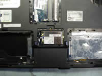 |
STEP 3
Unplug two wireless card antenna cables.
White cable - main, black cable - auxiliary.
Remove two screws securing the Wi-Fi card.
Carefully pull the Wi-Fi card from the slot and remove it. |
| |
|
 |
STEP 4
The modem card is located under the wireless card.
Remove two screws securing the modem card.
Lift up the card using the black belt to disconnect it from the mainboard.
Unplug the modem cable on the left side of the card.
Remove one screw (located in the RAM bay) securing the DVD drive. |
| |
|
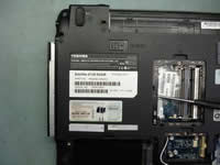 |
STEP 5
Carefully push the DVD drive from the laptop.
Remove the DVD drive.
|
| |
|
 |
STEP 6
Remove all marked screws from the bottom of the laptop. |
| |
|
 |
STEP 7
Lift up the keyboard bezel using a small flat-head screwdriver.
Continue removing the bezel with your fingers. |
| |
|
 |
STEP 8
Lift up and remove the keyboard bezel. |
| |
|
 |
STEP 9
Remove two screws securing the keyboard.
|
| |
|
 |
STEP 10
Lift up the keyboard and place it on the laptop cover so you can access the keyboard cable connector.
Unlock the connector and pull the cable.
Remove the keyboard. |
| |
|
 |
STEP 11
Remove two screws from the back side of the laptop. |
| |
|
 |
STEP 12
Unplug the video cable from the mainboard.
Pull the wireless card antenna cables through the hole in the mainboard.
Release the wireless card antenna cables.
Remove four screws securing the laptop hinges. |
| |
|
 |
STEP 13
Remove the LCD screen assembly. |
| |
|
 |
STEP 14
Remove three screws securing the top cover assembly to the laptop base.
Unplug the power button board cable, the touchpad cable and both speakers from the motherboard.
|
| |
|
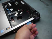 |
STEP 15
Using a guitar pick separate the top cover assembly from the laptop base assembly. |
| |
|
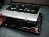 |
STEP 16
After all latches are released, lift up and remove the top cover assembly. |
| |
|
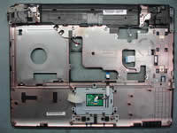 |
STEP 17
Here's a picture of the top cover assembly from the opposite side. |
| |
|
 |
STEP 18
Remove four screws securing the mainboard.
Unplug the USB board cable.
Release the power jack harness. |
| |
|
 |
STEP 19
Remove two hex studs from the VGA port on the side of the laptop. |
| |
|
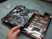 |
STEP 20
Start removing the mainboard from the right side. |
| |
|
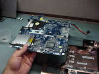 |
STEP 21
Lift up and remove the mainboard from the laptop base. |
| |
|
 |
STEP 22
Unplug the fan cable from the mainboard and turn the mainboard over. |
| |
|
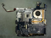 |
STEP 23
Remove four screws securing the CPU heatsink.
Lift up and remove the heatsink. |
| |
|
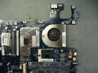 |
STEP 24
Remove one screw securing the cooling fan, slide the fan to the right and remove it.
Unlock the CPU socket by turning the screw-lock into "Open" position and carefully lift up the CPU from the socket. |
| |
|
|
|