|
Toshiba Qosmio F20/F25 disassembly. |
|
|
 |
STEP 1
Turn off the laptop, unplug the power adapter and remove the battery.
Remove the hard drive and memory doors. |
| |
|
 |
STEP 2
Remove four screws securing the hard drive cover.
Remove the cover.
|
| |
|
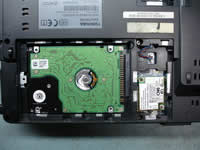 |
STEP 3
In order to disconnect the hard drive from the motherboard, carefully slide it to the left.
Lift up and remove the hard drive.
Remove two screws securing the dial-up modem card.
Lift up the modem and unplug the cable. Remove modem card.
|
| |
|
 |
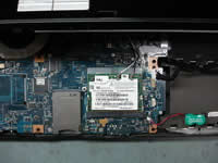
STEP 4
This notebook has two memory slots on the bottom and most likely both memory slots are occupied.
Remove both memory modules. |
| |
|
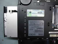 |
STEP 5
Remove two screws securing the DVD drive on the bottom of the notebook.
Carefully pull the DVD drive from the notebook and remove it.
By the way, you can open the DVD drive with a paper clip.
|
| |
|
 |
STEP 6
Start removing the hinge/speaker cover with a sharp object. You can use a small flathead screwdriver.
|
| |
|
 |
STEP 7
Remove the cover. |
| |
|
 |
STEP 8
Remove two screws securing the keyboard on the top. |
| |
|
 |
STEP 9
Lift up the keyboard as it shown on the picture. Be careful, the keyboard is still connected to the motherboard with a cable. |
| |
|
|
STEP 10
Place the keyboard upside down on the palm rest.
Remove one screw securing the metal cover.
Remove the cover. |
| |
|
 |
STEP 11
Now you can access the keyboard cable connector on the motherboard.
Unlock the connector by moving the brown clip about 2mm towards the screen.
Release the keyboard cable.
NOTE: the brown clip must stay attached to the white connector base. Be very careful with the connector.
|
| |
|
 |
STEP 12
Remove the keyboard.
|
| |
|
 |
STEP 13
Turn the laptop upside down and remove all screws from the bottom.
Unplug two cables pointed with red arrows. |
| |
|
 |
STEP 14
Remove two screws securing the display hinges. |
| |
|
 |
STEP 15
Remove one screw securing the power button board to the base.
Unplug the cable from the motherboard.
Slide the power button board to the left. |
| |
|
 |
STEP 16
Remove the power button board.
|
| |
|
 |
STEP 17
Remove two screws securing the top cover.
Unplug cables pointed with red arrows.
Release wireless card antenna cables (black and white cables).
|
| |
|
 |
STEP 18
There is one more screw hidden under the video cable. Remove the screw.
|
| |
|
 |
STEP 19
Carefully lift up the top cover assembly with the display.
The wireless antenna cables are still attached to the wireless card.
|
| |
|
|
STEP 20
The Wi-Fi antennas are connected to the wireless card. |
| |
|
 |
STEP 21
Remove one screw securing the wireless card cover.
Unplug the black cable.
Unplug the CMOS (RTC) battery.
Remove the wireless card cover. |
| |
|
 |
STEP 22
Unsnap both antenna cables from the wireless card.
Now you can remove the top cover assembly with display. |
| |
|
 |
STEP 23
Remove two screws securing the cooling fan.
Unplug the cooling fan cable from the motherboard. |
| |
|
 |
STEP 24
Remove the fan. |
| |
|
 |
STEP 25
Remove one screw securing the motherboard. |
| |
|
 |
STEP 26
Carefully start removing the motherboard from the base and flip it over on the desk.
The video graphics card is located on the other side of the motherboard. |
| |
|
 |
STEP 27
Remove two screws securing the video graphics card to the motherboard. |
| |
|
 |
STEP 28
Carefully pull the video graphics card from the slot.
If you are replacing the card, you'll have to transfer the heat sink to the new video card. |
| |
|
|
|


