 |
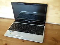
Toshiba Satellite L755, L755D, L750, L750D disassembly.
This guide explains only how to take apart the base assembly.
The screen removal procedure explained in the next guide. |
|
|
 |
STEP 1
Make sure the laptop is turned off before you start dismantling it.
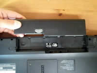
Unplug AC adapter. Unlock and remove laptop battery.
|
| |
|
 |
STEP 2
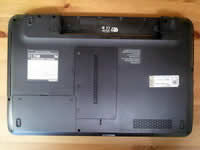
Unscrew five screws securing the hard drive cover and memory cover.
Lift up covers and remove them from the laptop.
|
| |
|
 |
STEP 3
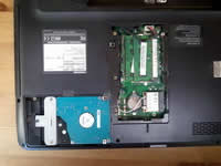
When both covers removed you can access the laptop hard drive, CMOS battery, wireless card and both memory modules.
It's not necessary to remove the wireless card and memory modules for the purpose of my guide. I'll leave them connected to the laptop.
Remove one screw securing the hard drive mounting bracket to the laptop case.
|
| |
|
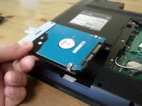 |
STEP 4
Slide the hard drive assembly to the left to disconnect it from the motherboard.
Lift up and remove the hard drive assembly.
Toshiba Satellite L755, L755D, L750, L750D laptops have a regular 2.5" SATA hard drive installed. If you are replacing the hard drive, you'll have to transfer the mounting bracket to the new drive. |
| |
|
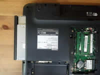 |
STEP 5
Remove one screw securing the DVD optical drive.
Pull the drive to the left to disconnect it from the motherboard.
Remove DVD drive. |
| |
|
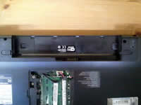 |
STEP 6
Remove one screw located in the battery compartment.
This screw securing the keyboard bezel. |
| |
|
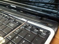 |
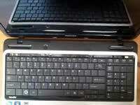
STEP 7
Turn the laptop over and carefully lift up the keyboard bezel with a small screwdriver.
Continue removing the bezel with your fingers. You'll have to wiggle it a little bit in order to separate from the laptop. |
| |
|
 |
STEP 8
Remove four screws securing the keyboard. |
| |
|
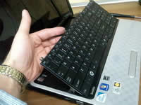 |
STEP 9
After all four screws removed you should be able to lift up the top side of the keyboard and turn it upside down.
Place the keyboard on the palmrest. Be careful, the keyboard still connected to the motherboard. |
| |
|
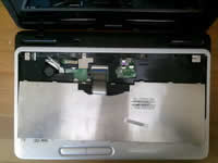 |
STEP 10
It's necessary to unlock the connector and release the cable before removing the keyboard.
In the following two steps I explain how to unlock the connector. |
| |
|
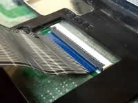 |
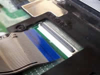
STEP 11
The connector has two pieces:
1. The white base which is soldered to the motherboard.
2. The brown locking tab - the moving part.
Carefully lift up the left side of the locking tab so it opens up at a 90 degree angle. |
| |
|
 |
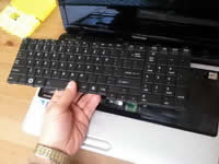
STEP 12
Now you can pull cable from the connector.
|
| |
|
 |
STEP 13
Remove the keyboard. |
| |
|
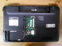 |
STEP 14
Remove shown screws from the bottom of the laptop. |
| |
|
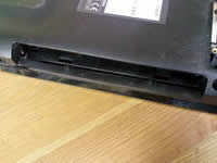 |
STEP 15
Don't forget two more screws in the DVD drive bay. |
| |
|
 |
STEP 16
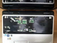
Remove screws securing the top cover assembly.
Disconnect the touchpad cable (1). Use same technique as for disconnecting the touchpad cable.
Disconnect the speaker cable (2). |
| |
|
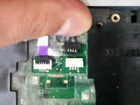 |
STEP 17
The speaker cable has a regular male-female type connector. |
| |
|
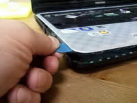 |
STEP 18
Start separating the top cover assembly from the laptop base using a piece of plastic (I'm using the guitar pick).
Continue separating the top cover from the base with your fingers. |
| |
|
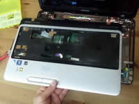 |
STEP 19
Remove the top cover assembly. |
| |
|
 |
STEP 20
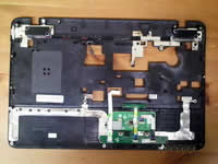
On the bottom part of the top cover you can access both speakers, touchpad and touchpad button board. |
| |
|
 |
STEP 21
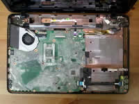
After the top cover assembly removed you can access the folloing internal laptop components:
- Power button board.
- DC jack.
- USB board.
- Motherboard. |
| |
|
 |
STEP 22
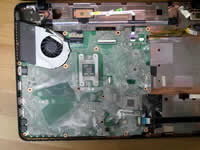
Remove three screws securing the motherboard and cooling fan assembly.
Disconnect the USB board cable (1) and power button board cable (2). Use same technique as for disconnecting the keyboard cable.
|
| |
|
 |
STEP 23
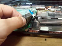
Carefully unglue the protective film from the laptop case. |
| |
|
 |
STEP 24
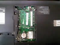
In order to remove the motherboard it's necessary to disconect the DC jack cable and both wireless card antennas.
They are located under the memory cover which we removed in the step 2. |
| |
|
 |
STEP 25
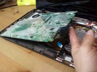
Start removing the motherboard as it shown on the picture. |
| |
|
 |
STEP 26
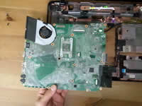
Remove motherboard from the laptop base. |
| |
|
 |
STEP 27
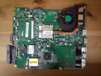
On the bottom side of the motherboard you can access the cooling fan assembly and CMOS battery (on the left side from the wireless card). |
| |
|
 |
STEP 28
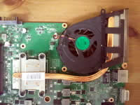
In order to remove the cooling fan assembly (fan and heatsink) you'll have to loosen four screws and disconnect the fan cable.
After that carefully lift up the assembly and separate it from the processor. |
| |
|
 |
STEP 29
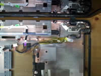
The DC jack is attached to the harness.
If the DC jack failed, you can remove the whole harness and replace it with a new DC jack harness. |
| |
|
|
|