|
Toshiba Portege 4010 disassembly.
|
|
|
 |
STEP 1
First of all, remove the laptop battery.
|
| |
|
 |
STEP 2
Remove two screws securing the wireless card cover.
Remove two screws securing the HDD cover.
Remove all covers.
|
| |
|
 |
STEP 3
Disconnect the wireless card cables.
Remove the wireless card.
Remove the hard drive.
Remove the DVD drive. |
| |
|
 |
STEP 4
Remove all marked screws on the bottom. |
| |
|
 |
STEP 5
Turn the computer right side up.
Insert a thin object under the securing strip and lift it up.
Release the securing strip latches with your fingers.
|
| |
|
 |
STEP 6
Lift up the keyboard securing strip and remove it. |
| |
|
 |
STEP 7
Remove two screws securing the keyboard and lift up the keyboard out of the base. |
| |
|
 |
STEP 8
Disconnect the keyboard cable on the system board.
Remove the keyboard. |
| |
|
 |
STEP 9
You will find the memory stick under the mylar cover. Remove the memory cards. |
| |
|
|
STEP 10
Disconnect the left speaker cable on the system board.
Pull the wireless card cables through the opening.
|
| |
|
 |
STEP 11
Disconnect the right speaker cable on the system board.
|
| |
|
 |
STEP 12
Remove three screws securing the palmrest. |
| |
|
 |
STEP 13
Release the latches securing the palmrest.
To separate the top cover and the base you can use a guitar pick. |
| |
|
 |
STEP 14
Lift the palmrest and turn it over.
Disconnect the flat cable on the system board.
Remove the palmrest.
|
| |
|
 |
STEP 15
Remove eight screws securing the upper cover assembly.
Disconnect the display cable on the system board.
|
| |
|
 |
STEP 16
Lift the display assembly off the base. |
| |
|
 |
STEP 17
Remove two screws securing the sound board.
Remove the sound board with the microphone. |
| |
|
 |
STEP 18
Remove two screws securing the modem card.
Disconnect the modem card cable on the system board.
Remove the modem card with the cable. |
| |
|
 |
STEP 19
Disconnect two cables on the system board.
|
| |
|
|
STEP 20
Disconnect the RTC battery cable on the system board.
Remove the RTC battery.
Disconnect the BlueTooth switch board cable on the system board.
|
| |
|
 |
STEP 21
Remove two screws securing the system board.
|
| |
|
 |
STEP 22
Lift the system board to disconnect it from I/O board.
|
| |
|
 |
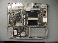
STEP 23
Lift the system board off the base. |
| |
|
 |
STEP 24
Remove six screws securing the I/O board. |
| |
|
 |
STEP 25
Lift the I/O board with cables off the base. |
| |
|
 |
STEP 26
Unplug and remove the modem and LAN cables. |
| |
|
 |
STEP 27
Done !!!
|
| |
|
|
|


