|
Toshiba Tecra A1 disassembly. |
|
|
 |
STEP 1
Turn the unit upside down.
Remove screws securing the CPU cover, the modem cover, the memory cover, the hard drive cover, the wireless card cover.
Remove all covers.
|
| |
|
 |
STEP 2
Remove the memory card, the wireless card (if you have any), the battery.
|
| |
|
 |
STEP 3
Remove the screw securing the hard drive.
Remove the hard drive. |
| |
|
 |
STEP 4
Remove two screws securing the fan assembly.
Disconnect the fan cable on the system board.
Lift the fan out of the base. |
| |
|
 |
STEP 5
Remove four screws securing a plate over the cooling module.
Remove the plate.
|
| |
|
 |
STEP 6
Carefully lift the cooling module off the CPU. |
| |
|
 |
STEP 7
Remove the old grease covering the CPU. |
| |
|
 |
STEP 8
Turn the laptop upside down
Remove all marked screws on the bottom of the notebook. |
| |
|
 |
STEP 9
Turn the computer right side up.
Insert a thin object under the securing strip and lift it up.
Be careful, it may be very tight.
|
| |
|
|
STEP 10
Remove the securing strip.
|
| |
|
 |
STEP 11
Remove three screws and the keyboard lock in the center.
|
| |
|
 |
STEP 12
Lift the keyboard and place it upside down on the palmrest.
Remove one screw securing a metal plate.
Remove the plate.
|
| |
|
 |
STEP 13
Disconnect the keyboard cable on the system board. |
| |
|
 |
STEP 14
Remove the keyboard. |
| |
|
 |
STEP 15
Remove one screw on the back of the computer.
|
| |
|
 |
STEP 16
Remove the screw securing the DVD-rom. |
| |
|
 |
STEP 17
Remove the DVD-rom. |
| |
|
 |
STEP 18
Disconnect the LCD cable on the system board.
Disconnect the speaker cables on the system board. |
| |
|
 |
STEP 19
Pull the wireless LAN cables through the opening. |
| |
|
|
STEP 20
Lift the upper cover and display assembly off the base. |
| |
|
 |
STEP 21
Remove the upper cover and display assembly.
|
| |
|
 |
STEP 22
Disconnect the touchpad cable on the system board.
Remove the screw securing the touchpad.
Lift the touchpad off.
|
| |
|
 |
STEP 23
Remove two screws securing the plastic frame.
Remove the plastic frame. |
| |
|
 |
STEP 24
Turn the unit upside down.
Remove two screws securing the modem board.
Disconnect the cable.
Remove the modem board. |
| |
|
 |
STEP 25
Turn the computer right side up.
Remove two screws securing the system board to the base.
|
| |
|
 |
STEP 26
Carefully lift the system board off the base.
Disconnect and remove RTC battery.
Disconnect and remove DC jack cables. |
| |
|
 |
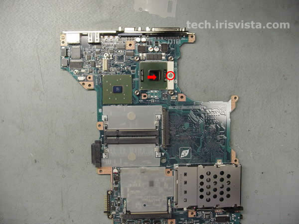
STEP 27
Unlock the CPU.
Remove the CPU. |
| |
|
 |
STEP 28
DONE ! |
| |
|
|
|