|
Toshiba Portege R100 disassembly. |
|
|
 |
STEP 1
Start the notebook disassembly with removing the battery.
|
| |
|
 |
STEP 2
Remove a plastic "dummy" PC card.
Remove one screw securing the memory module cover and remove the cover.
Remove two screws securing the hard drive cover and remove the cover.
|
| |
|
 |
STEP 3
Remove the memory stick.
Carefully lift up the hard drive, turn it over and disconnect the hard drive cable. |
| |
|
 |
STEP 4
Remove all screws securing the bottom of the notebook. |
| |
|
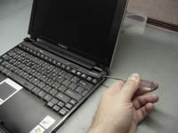 |
STEP 5
Turn the notebook the right side up.
Start removing the keyboard securing strip with a sharp object.
|
| |
|
 |
STEP 6
Release the keyboard strip plastic latches with your fingers and remove the securing strip.
|
| |
|
 |
STEP 7
Remove two screws securing the keyboard.
|
| |
|
|
STEP 8
Lift up the keyboard and place it upside down on the palmrest.
Disconnect the flat keyboard cable on the system board. |
| |
|
 |
STEP 9
Disconnect LED cable, sound board cable and touchpad cable on the system board.
Remove five screws securing the top assembly to the base assembly.
|
| |
|
 |
STEP 10
Start separating the notebook top assembly and the base assembly.
|
| |
|
 |
STEP 11
Do not forget to release the latch in the battery bay. |
| |
|
 |
STEP 12
Remove the notebook base assembly. |
| |
|
 |
STEP 13
Remove tape securing connectors.
|
| |
|
 |
STEP 14
Remove two screws securing the PC card connector to the system board.
Disconnect the PC card connector cable on the system board.
Remove the PC card connector.
|
| |
|
 |
STEP 15
Remove two screws securing the modem card and the hard drive flex cable.
Remove the modem card.
Disconnect the hard drive flex cable on the system board and remove it. |
| |
|
|
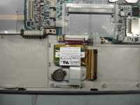
STEP 16
Disconnect the speaker and the RTC (CMOS) battery cables on the system board.
|
| |
|
 |
STEP 17
Disconnect the modem and LAN jacks cable on the system board.
Remove the modem/LAN jacks.
|
| |
|
 |
STEP 18
Carefully lift up the wireless card board to disconnect it from the system board and turn it over.
|
| |
|
 |
STEP 19
Disconnect the video cable and the FL inverter cable on the system board.
Remove two screws securing the system board to the top cover assembly. |
| |
|
 |
STEP 20
Remove the notebook system board. |
| |
|
 |
STEP 21
The heatsink and the fan are a part of the system board and I'm not going to remove them.
|
| |
|
 |
STEP 22
Toshiba Portege R100 notebook disassembled!
|
| |
|
|
|


