|
Toshiba Satellite M35, M30 disassembly.
|
|
|
 |
STEP 1
Unlock the battery and remove it from the notebook.
|
| |
|
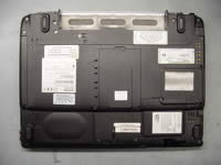 |
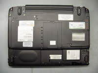
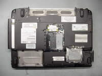
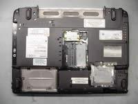
STEP 2
Remove the hard drive cover, the memory module cover and the wireless card cover on the bottom of the notebook.
|
| |
|
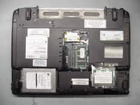 |
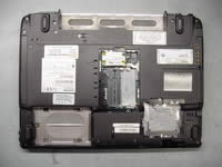
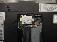
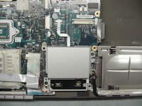
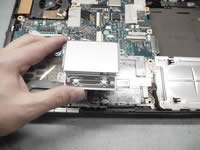
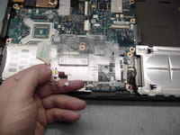
STEP 3
To remove the hard drive, slide it away from the connector and lift it up.
Remove the memory module.
Disconnect the wireless card antenna cables and remove the wireless card. |
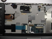
| |
|
 |
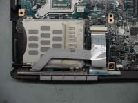
STEP 4
Remove two screws securing the DVD drive to the notebook base. |
| |
|
 |
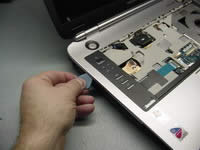
STEP 5
Slide the DVD drive away from the notebook and remove it.
Remove the "dummy" PC card.
|
| |
|
 |
STEP 6
Remove nineteen screws on the bottom of the notebook. |
| |
|
 |
STEP 7
Remove two screws securing the modem card to the system board.
Carefully lift it up to disconnect from the system board and disconnect the cable on the modem card. |
| |
|
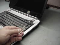 |
STEP 8
Place the notebook the right side up.
Using a screwdriver or another sharp object start removing the keyboard securing strip. |
| |
|
 |
STEP 9
Remove the keyboard securing strip. |
| |
|
|
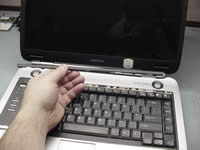
STEP 10
Remove three screws and two keyboard locks securing the keyboard.
Lift up the keyboard and place it upside down on the palmrest.
|
| |
|
 |
STEP 11
Remove one screw securing a metal plate over the keyboard connector and remove it.
|
| |
|
 |
STEP 12
Turn the keyboard the right side up so you can access the keyboard cable.
Disconnect the keyboard cable on the system board and remove it from the notebook.
|
| |
|
 |
STEP 13
Remove four screws securing the top cover assembly to the notebook base.
|
| |
|
 |
STEP 14
Disconnect the following cables on the system board (from top to bottom):
Antenna cables.
Display video cable.
Microphone cable.
Power switch cable.
Notebook lid close switch cable.
|
| |
|
 |
STEP 15
Release the top cover latches by moving a guitar pick along the edge.
|
| |
|
 |
STEP 16
Lift off the top cover and display assembly starting from the back of the notebook. |
| |
|
 |
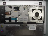
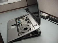
STEP 17
Remove the top cover/display assembly.
|
| |
|
 |
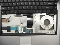
STEP 18
Remove two screws securing the touchpad.
Disconnect the touchpad cable on the system board.
|
| |
|
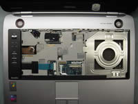
 |
STEP 19
Remove the touchpad.
|
| |
|
|
STEP 20
Disconnect the CMOS battery cable and the sound board cable on the system board.
|
| |
|
 |
STEP 21
Remove the touchpad holder.
|
| |
|
 |
STEP 22
Remove one screw securing the CD player switch board to the system board.
Disconnect the flat cable on the system board.
Remove the switch board.
|
| |
|
 |
STEP 23
Remove securing tape from the connectors. |
| |
|
 |
STEP 24
Disconnect all cables marked with red arrows on the system board.
Remove three screws securing the system board to the notebook base. |
| |
|
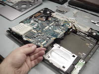 |
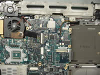
STEP 25
Start removing the system board by lifting the right side. |
| |
|
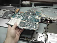 |
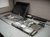
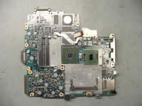
STEP 26
Remove the system board from the notebook base. |
| |
|
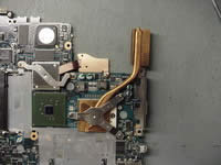 |
STEP 27
Remove three screws securing the CPU heatsink.
Remove the heatsink.
|
| |
|
 |
STEP 28
Unlock the CPU and carefully remove it from the socket on the system board.
|
| |
|
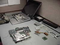 |
STEP 29
Toshiba Satellite M35 notebook disassembly done.
|
| |
|
|
|


